Part 2 In The Series:
Overlooked Essentials in Geothermal Energy
TABLE OF CONTENTS
Introduction
What is Ground Temperature Creep?
How Far Away is the Ground Temperature Changing?
What is ΔT (aka. Delta T)?
The Simplest Case
3 Illustrative Examples
Test #1. Grouted U-Loop
Conventional Geothermal Loop
Conventional Shallow Geothermal Loop – Transient
Test #2. Shallow Pile
Geothermal Pile Example
Test #3. Single Pipe
Pipe Size Comparison
Pipe Length Comparison
Fluid Flow Rate Comparison
Key Findings:
Across three different tests, we found that a small change in ground temperature – even far away from the in-ground heat exchanger – can have a direct impact on the fluid temperature within the geothermal system. In cases where the system is particularly sensitive to ground temperature (ie. a very long pipe) a 1°C increase/decrease in ground temperature results in a 1°C increase/decrease in fluid temperature change (ΔT).
This one-to-one relationship means the key findings from our ΔT blog post are also true here:
400,000 kWh
Annual Energy that may be lost or gained per °C change
$100,000
Annual Energy Cost that may be saved or lost per °C change
80,000 kg
ANNUAL CO2 THAT MAY BE EMITTED PER °C CHANGE
Introduction:
What is the cost of over or under estimating the ground temperature of a geo-exchange system in the design process by just 1°C from reality?
If you know what effect a given change in the ground temperatures around a geothermal (also known as geo-exchange or “earth conditioning”) system will produce on the fluid temperatures in the system, then you can use our previous ΔT blog post to determine the cost or benefit of that change in terms of heat exchange capacity and dollars. This blog post is designed to allow you to put a dollar value on the potential errors and inaccuracies that might exist in estimates, predictions, or measurements of ground temperatures around a geothermal system.
Ground source heat pump (GSHP) systems, consisting of heat pumps and ground heat exchangers, are typically designed to extract the heat from buildings in summer and transfer it into the ground (cooling mode), then in winter to extract the heat from the ground and transfer it into the buildings (heating mode).
When analyzing the performance of ground heat exchangers (often called boreholes or piles depending on their design), most studies focus on evaluating the:
1. Effects of in-ground heat exchanger depths, diameters and separation
2. Influence of different pipe configurations and material
3. Effects of different grout and soil thermal properties
4. Ground temperature changes caused by the GSHP operation or annual building loads
However, in this blog, the focus is on the effect of a 1°C change in ground temperature on the fluid temperature change ΔT as it travels through the pipe, while the soil, geometry, and flow conditions are kept the same.
We are trying to answer the question…
If the ground temperature around my geothermal system changes 1°C more than I was expecting (or is different in reality by that much from what I designed for), how much will I gain or lose financially, and in terms of heat exchange potential? Is a mere 1°C ground temperature change/error significant, or can it be ignored?
There are a multitude of reasons why ground temperatures can change unexpectedly (see the next section for one common reason). And there are many ways that engineering estimates, simulations, and predictions of ground temperatures can have very large divergences from reality (some little-known reasons for which we will explore in our next blog post). The trends we discuss in this blog post apply regardless of the reason for the ground temperature change or error.
What is Ground Temperature Creep?
Probably the most common and important cause of ground temperature changes surrounding a geothermal system is feedback from the geothermal system itself.
Systems with imbalanced loads, where the amount of heating energy extracted from the ground (heating season) is not equivalent to the amount of heating energy dumped into the ground (cooling season) will tend to cause the average ground temperatures around the in-ground heat exchanger to change over time (the direction of the change depending on the type of imbalance in the load). This type of temperature change is a bad thing 99% of the time (although we might be able to use it to keep permafrost frozen). The system will become less and less efficient at its most important task (either heating or cooling) over time, until eventually it can no longer function at all.
The results of our tests here, combined with our previous ΔT blog post, can be used to determine how much money and performance will be lost with a given amount of “ground temperature creep.” Any monetary amounts mentioned in this case are direct costs/losses and any heat exchange capacity amounts mentioned are reductions in system performance.
Note:
If a system is experiencing undesirable “ground temperature creep” it may be tempting to increase the flow rate of the fluid in the system to maintain a desired fluid temperature range. However, increasing flow rates in this situation can actually accelerate the ground temperature creep, leading to a downward spiral of ever-increasing flow rates and ever worsening ground temperatures until the system can no longer physically function.
How Far Away is the Ground Temperature Changing?
We will be exploring the effect of ground temperature changes directly touching the geothermal pile/pipe, and also the mean ground temperature changes happening in the soil up to several meters away from the geothermal pile/pipe.
Quantifying the effect of distant ground temperature changes on a geothermal system has to be done on a per-site basis, as the thermal properties of the soil have a huge impact on the speed and the magnitude of the ground temperature change that will actually reach the geothermal pipe surface, where it can impact the fluid temperatures. However, in practice it may be more practical to know or measure the temperature of the ground farther from the in-ground heat exchanger, at a point where it is not affected by the operation of the geo-exchange system (we’ll call this the “far point” in the ground). We give examples at both of these distances, with some real-world soil properties, in order to give you a rough idea of what to expect whether you know the temperature directly touching the heat exchanger, or further away in the ground.
What is ΔT (aka. Delta T)?
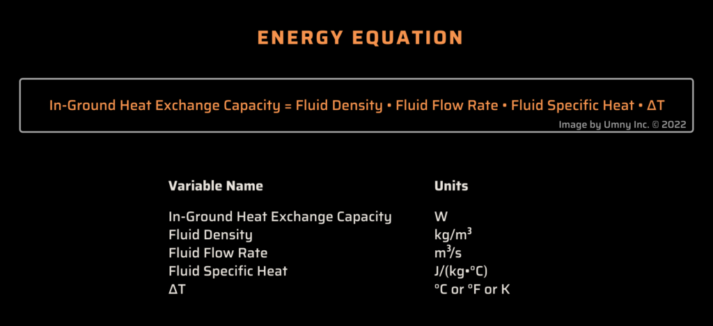
ΔT is simply the difference between the temperature of the fluid when it enters the geothermal ground loop and the temperature of the fluid when it exits the geothermal ground loop (ΔT = Tin – Tout). This value, along with flow rate, determines how much heat exchange the ground loop is producing (essentially the performance of the geothermal system). Refer to our previous blog post for more information about ΔT and its impact on the profitability of geothermal systems.
We use ΔT to calculate the in-ground heat exchange performance with the following energy equation:
The Simplest Case:
The longer the fluid in the geothermal system stays in contact with the ground the closer its temperature will get to the average ground temperature, and after a certain amount of time the difference between the fluid temperature and the average ground temperature will be essentially zero. In fact, there are many real-world situations in which this occurs due to low fluid flow rates, extremely high heat exchange ability, and/or long in-ground pipe lengths. In these situations, a change in the average ground temperature of 1°C will produce an equivalent 1°C change in the geothermal system’s ΔT (it’s a one-to-one relationship).
3 Illustrative Examples:
The interaction between ground temperatures and the ΔT of a geothermal system is quite complex. In order to get an exact value for how a much 1°C change in ground temperature will affect a system’s ΔT you would need to know the following variables:
- Where exactly, geometrically, is this 1°C ground temperature change occurring?
- What are the thermal properties of the soil (density, thermal conductivity, specific heat), and what are the actual soil temperatures at all points around the geothermal system?
- What is the geothermal ground-loop system made of and what are its dimensions (pipe materials and sizes, grout type and thickness, etc)?
- What type of fluid is being used in the loop, how fast is it flowing, and what is its temperature when entering the loop?
In order to provide some sort of answer to the question “How much will ΔT change with a 1°C change in ground temperatures?” that is relevant to you, without knowing your specific situation, we are going to look at some case studies of typical geothermal system configurations, as well as a classical pipe-flow heat exchange equation.
If the situation you are looking at is wildly different than our examples here, we at least hope to convey the fact that ground temperature changes even as small as 1°C are important in most cases. You can then use a CFD model or some other method to check your unique situation, without simply assuming that small ground temperature changes/differences are not worth looking at.
We are able to explore situations like this using CFD modelling, using all of the variables listed above, and get very accurate values for ΔT. Contact us for more information.
Test #1. Grouted U-Loop:
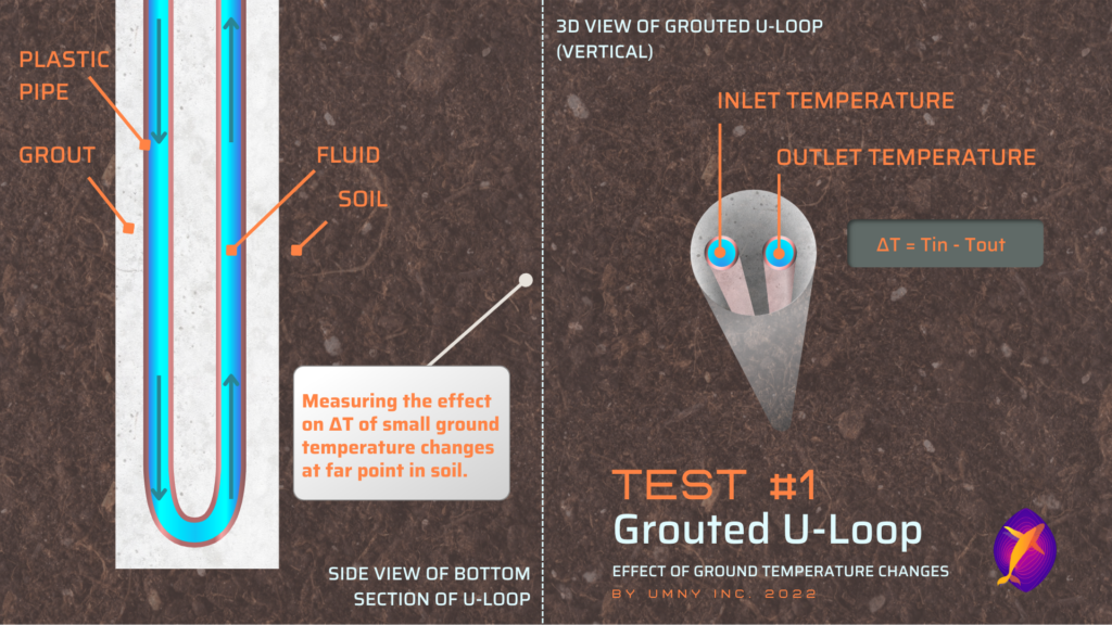
For this example, we are using a steady-state CFD model of one of the most common types of vertical in-ground heat exchangers, a grouted u-loop, and changing the average ground temperature several meters away from the system by 1°C to measure what changes in the fluid temperatures occur. In this case, the far point of the soil has one constant temperature across the whole length of the u-loop (such as the mean ground temperature for that region).
Conventional Geothermal Loop:
As the ground temperature at a far point from the u-loop changes, this change affects the volume of soil between that point and the in-ground heat exchanger – traveling through the walls of the grout and pipe to eventually change the fluid temperature.
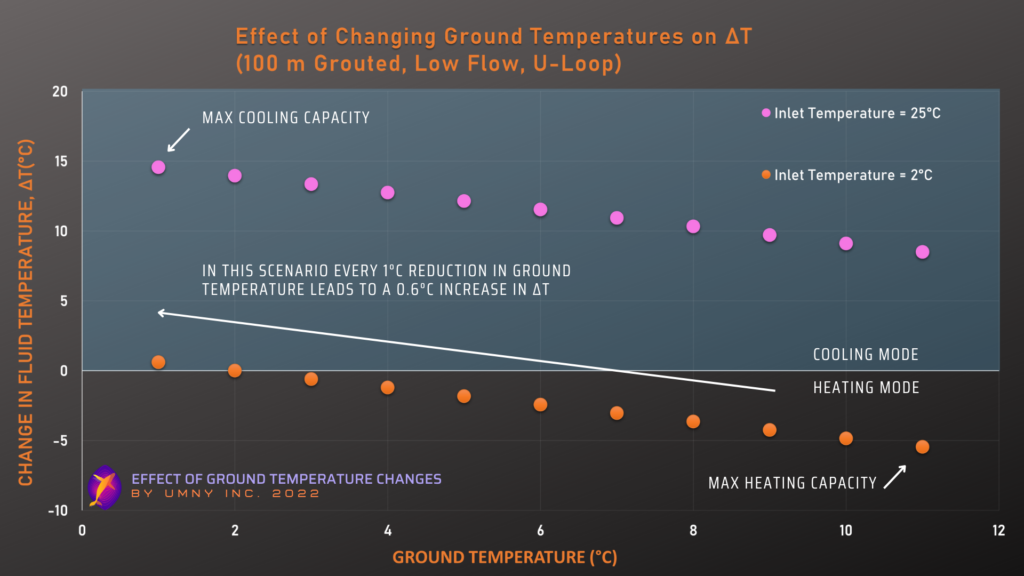
The fluid temperature going in to the u-loop is constant (in this test, we keep it constant at 25°C and 2°C to simulate cooling and heating modes respectively). The only variable that changes is the far ground temperature. Therefore, the changes in fluid temperature that we see in the following chart are fully due to the ground temperature effects.
Details of Deep Grouted U-Loop Test
| Fluid Flow Rate | 2 L/min |
| Pipe Size | 2″ |
| Design | Vertical Grouted U-Loop |
| Length of Loop | 100 m |
| Horizontal Distance to Soil Temp. Change Point | 5 m |
| Study Type | Steady State |
As you can see from the graph above, in a very standard geothermal system, a 1°C change in the average ground temperature 5 meters away from the system produces about a 0.6 °C change in the ΔT of the system (refer to our previous ΔT blog post to see how this might impact the system’s performance and profitability).
Example of the effects of these results:
If this conventional u-loop system was designed for a far point ground temperature of 7°C, the capacity could have been estimated to be 423 W in heating and 1,522 W in cooling (using the energy equation above).
But what if the mean ground temperature was actually 8°C on the site where the system was built? Or that over time, the ground temperature crept up to 8°C? In the conditions of this test, that would mean the real-world capacity would be 507 W more in heating capacity and 1,437 W less in cooling capacity per u-loop.
423 W – 507 W = 84 W less heating per hour
84 W less heating per hour * 8760 hours per year / 1000 Wh per kWh = 732 kWh less heating per year (rounded after)
Multiplying the difference between these steady state capacities across the number of hours in a year means that just this one u-loop is producing 732 kWh more heating, and 742 kWh less cooling in a year than it was designed for. Considering many geothermal designs have up to hundreds of u-loops within them, the entire system might now be undersized for its cooling load or oversized for its heating load. This project could have been designed more cheaply, efficiently or reliably. In this way, the ground temperature estimation before the system is installed must be as accurate as possible to avoid wasting materials and costs, or building a system that won’t work as expected.
Conventional Shallow Geothermal Loop – Transient:
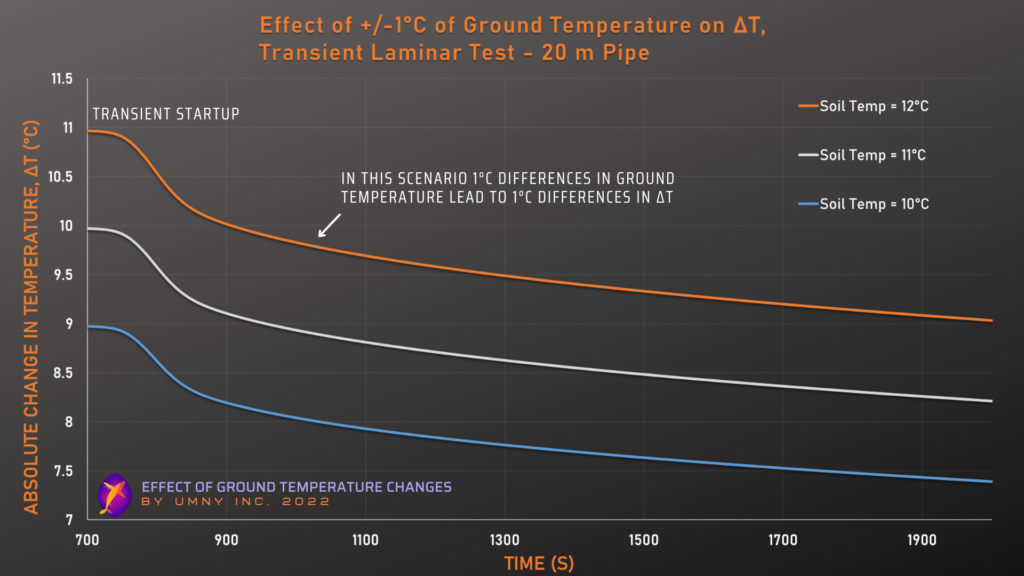
This is a demonstration from a CFD model of a conventional u-loop geothermal system, but shallower than the example above (only 20 meters). Using a transient simulation we can show how temperatures change over time. We explore the same system setup with two different flow rates – one is a low flow rate (laminar), and the other is a high flow rate (turbulent). We track the changes to the outlet temperature over time based on increasing or decreasing the average ground temperature 2 meters away from the piping, while the inlet fluid temperature remains constant.
This first graph and table are for the slow flow case, and the next ones are for the turbulent case.
Details of Shallow Laminar Grouted U-Loop Test
| Fluid Flow Rate | 0.5 GPM |
| Pipe Size | 1″ |
| Design | Vertical Grouted U-Loop |
| Length of Loop | 20 m |
| Horizontal Distance to Soil Temp. Change Point | 2 m |
| Study Type | Transient |
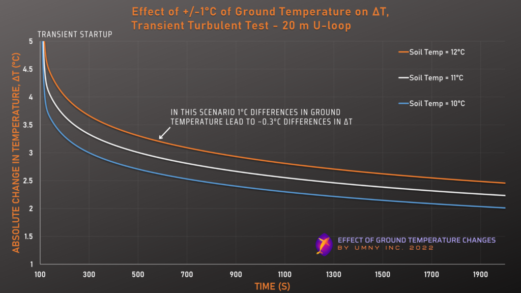
Details of Shallow Turbulent Grouted U-Loop Test
| Fluid Flow Rate | 4 GPM |
| Pipe Size | 1″ |
| Design | Vertical Grouted U-Loop |
| Length of Loop | 20 m |
| Horizontal Distance to Soil Temp. Change Point | 2 m |
| Study Type | Transient |
The above two graphs clearly demonstrate the importance of flow rate in determining how much ground temperature changes will affect ΔT in a geothermal system. The first graph shows that with a 1°C ground temperature change, the system’s ΔT also changes by almost exactly 1°C (this is an example of what is described in “The Simplest Case” section above), because the fluid is in contact with the ground for so long due to the low flow rate. Whereas the second graph shows that the system’s ΔT only changes by about 0.4°C for a 1°C change in ground temperatures, because the fluid is not spending as much time in contact with the soil (due to the high flow rate) and is therefore less influenced by soil temperatures. The above two graphs also demonstrate that the trends we discuss in this blog post hold up in transient simulations, not just steady-state.
However, as far as the whole system’s actual heat exchange performance is concerned, the effect of a 1°C ground temperature change may be the same for these two scenarios. This is because the heat exchange of the system is determined by the ΔT times the mass flow rate (using the energy equation above). So for the second graph, even though the ΔT change is smaller, the flow rate is higher, meaning that small changes in ΔT have an amplified effect on the actual heat exchange occurring. Please refer to our previous ΔT blog post for more details on this.
Test #1 shows that for this typical ground heat exchanger system, small changes in the ground temperature (even far away from the pipes) can have an equally significant change on the heat exchange performance of the u-loop. This was shown for a deep and shallow case, steady state and transient, and for laminar and turbulent cases.
Test #2. Shallow Pile:
In this test we used one of our real-world validated CFD models of a geothermal vertical pile system (generally shallower than conventional geothermal systems) to demonstrate the effect of 1°C of ground temperature change at 5 meters away from the pile.
When we talk about changing the ground temperature by 1°C in this example, it means that we change the ground temperature profile for the entire depth of the geothermal system by 1°C, at a certain distance from the system, simulating a change in the ambient/surrounding ground temperature (which varies by depth and season).
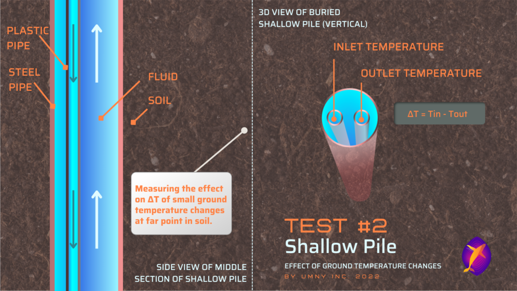
Geothermal Pile Example:
With a constant flow rate, we change the inlet fluid temperature to simulate a range of operating cases. These cases occur in a baseline ground temperature scenario, and then in +1°C/-1°C scenarios where the values of ground temperature across the by-depth profile are each increased/decreased by 1°C. The following graph plots the changes to the outlet temperature that happen in these three ground scenarios.
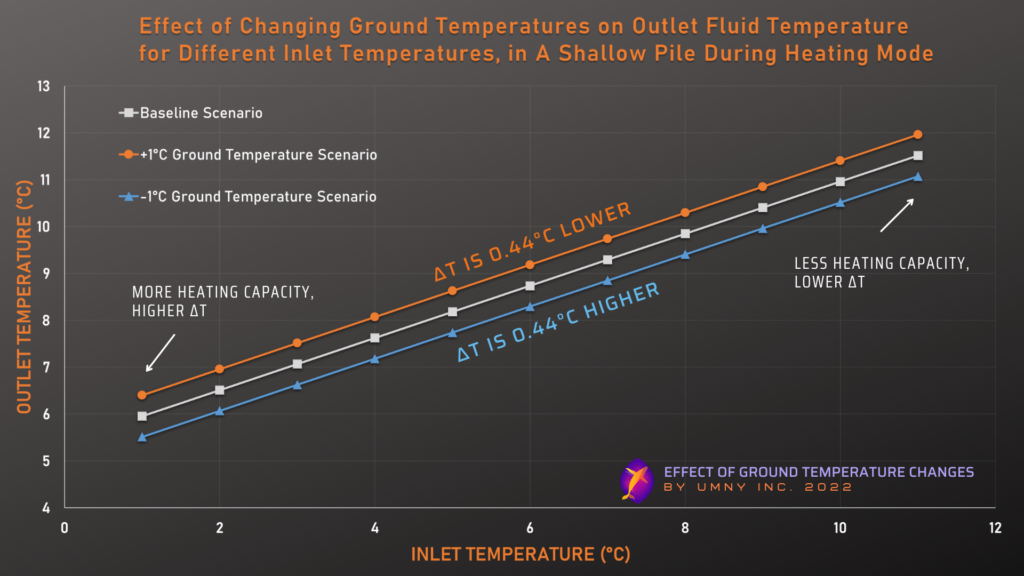
Details of Shallow Pile Test
| Fluid Flow Rate | 2 L/min |
| Inlet Pipe Size | 1″ |
| Design | Pile |
| Length of Loop | 20 m |
| Horizontal Distance to Soil Temp. Change Point | 2 m |
| Study Type | Steady State |
As the graph above shows, in this scenario a 1°C ground temperature change at a distance of 5 meters away, produces about 0.44°C of change in the geothermal pile’s ΔT. The very different design of a geothermal pile vs a grouted u-loop (and the difference in the distance to the ground temperature change) will mean that ground temperatures do impact the system at a different magnitude. However, this relatively small change in ΔT still means that this system would produce 9% more heating capacity per pile if the baseline ground temperature profile 5 meters away was only 1°C higher than reality.
Test #3. Single Pipe:
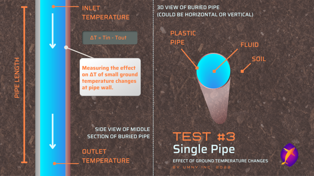
In this test we use the traditional heat transfer calculations applied to fluid moving within a pipe. This traditional model may be too simplistic to be used for determining actual system performance of real-world geothermal (with more complicated geometries), but it is useful here for giving us some information about what factors affect the degree to which 1°C of ground temperature change can impact the ΔT. As well, this test may be directly applicable to some horizontal geothermal systems, or to any case where there is a buried pipe (either horizontal or vertical) in contact with the surface of the ground which might experience heat loss – including plumbing lines and uninsulated geothermal distribution pipes.
Unlike the other two tests, here we are checking the effect of ground temperature changes happening directly at the surface of the pipe wall. We will be looking at the changes to ΔT and comparing different scenarios with variable:
- pipe diameters
- pipe lengths
- fluid flow rates
The equation/model used for the following examples is described in “Heat and Mass Transfer” by White, Frank M, section 8.3. It is a standard equation used in thermodynamics, frequently referred to as the model of “heat loss of fully developed internal flow through a circular pipe.”
Pipe Size Comparison:
First, we graph the magnitude of the impact of ground temperature changes on pipes with two very different diameters (¾” and 6” diameters). The y-axis for this and the following graphs plots the ground temperature minus the inlet temperature, to normalize the relationship between ground temperature and ΔT (which is on the x-axis). The more extreme the curve, or the higher the magnitude of the point, the more impact ground temperature has had on the performance of the system.
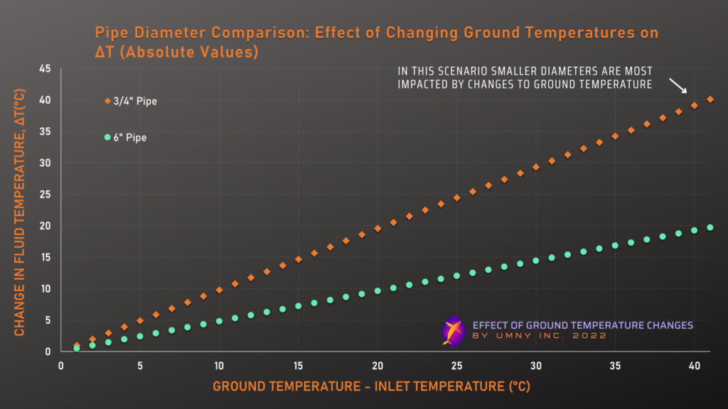
Details of Single Pipe – Diameter Test
| Fluid Flow Rate | 2 L/min |
| Pipe Diameter | Variable |
| Pipe Length | 20 m |
This graph demonstrates the effect that pipe diameter has on the ground temperature to fluid temperature relationship. Smaller diameter pipes are more affected by changes to ground temperatures than larger diameter pipes, especially when there is a big difference between the ground and fluid temperatures.
Pipe Length Comparison:
The next graph compares the effect of ground temperature on pipes with different lengths.
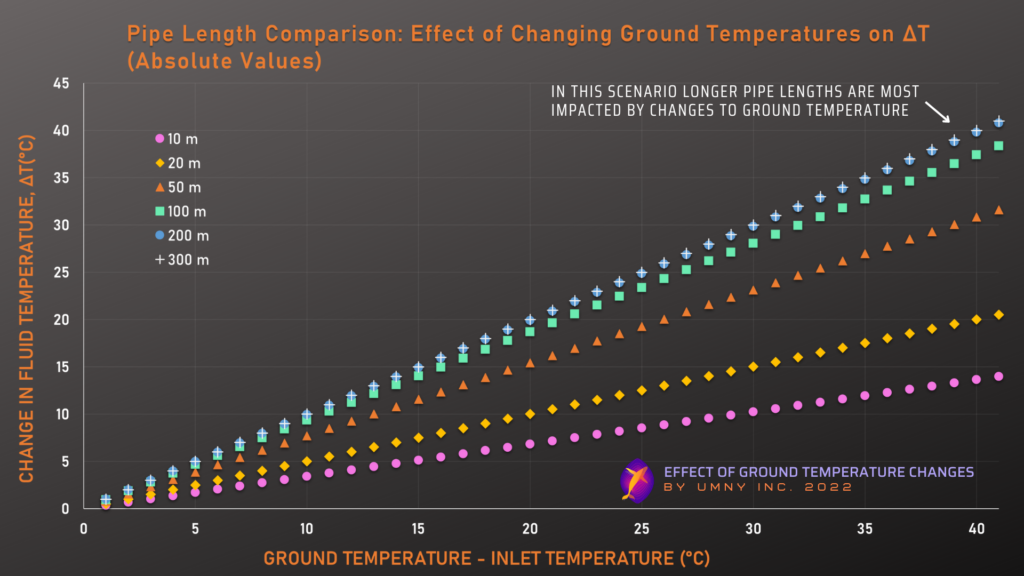
Details of Single Pipe – Length Test
| Fluid Flow Rate | 2 L/min |
| Pipe Diameter | 2″ |
| Pipe Length | Variable |
This graph demonstrates the influence that pipe length has on the relationship between ground temperatures and fluid temperatures. As explained in the “The Simplest Case” section above, the longer the fluid in the in-ground heat exchanger is in contact with the ground, the more it will tend to match the average temperature of that ground. This explains why we see in the graph above that longer pipes are more influenced by ground temperature changes, and it also demonstrates that, for the variables chosen in this demonstration, the ground and the pipe fluid reach equilibrium somewhere between 100 and 200 meters.
Fluid Flow Rate Comparison:
We will again compare the ground temperature effects at different flow rates in the next graph. This time we are covering laminar, transitional, and turbulent zones. The equations used to calculate the heat loss are modified to reflect the appropriate calculations for these flow conditions.
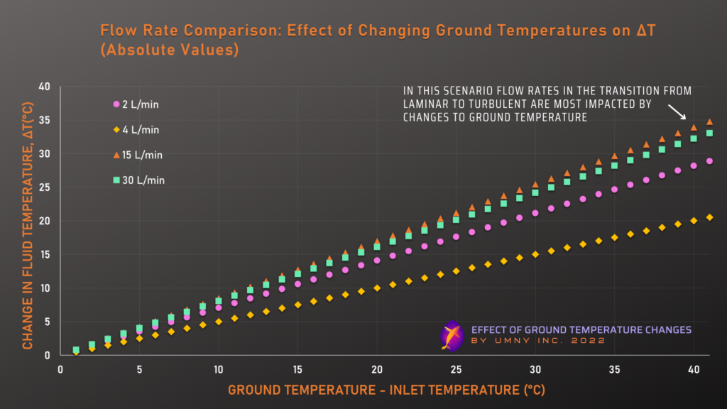
Details of Single Pipe – Flow Rate Test
| Fluid Flow Rate | Variable |
| Pipe Diameter | 2″ |
| Pipe Length | 20 m |
This graph demonstrates how the fluid flow rate influences the relationship between ground temperatures and fluid temperatures. Although fluids that spend a longer time in the ground loop (ie. those with lower flow rate) will tend to be more influenced by the ground temperature, the relationship becomes more complex because of the differences between laminar and turbulent flows. Turbulent flows cause the fluid to mix more, leading to more rapid heat exchange with the ground, which can counteract the reduced time spent in the ground loop. For the variables explored in this example it appears that a turbulent/transitional flow somewhere around 15 L/min is the most heavily impacted by changes in ground temperatures, and fast laminar flows are the least impacted.
How Does This Apply to Your Situation?
As we have mentioned, to get an accurate idea of how much 1°C of ground temperature change might affect the geothermal system you have in mind probably requires a custom built CFD model (contact us for more information), however we can use the examples we have given above to get a rough estimate for many situations.
Simple Example:
Let’s say, for example, you are working with a conventional geothermal “grouted u-loop” system, but the loops go down to 150 meters. You can look at our first example, which is a 100 meter “grouted u-loop” system, and which shows a 0.6°C change in ΔT for each 1°C change in distant surrounding ground temperature. Looking at the relationships shown by the equation results above (our last examples) we know that as the total pipe length becomes longer, the fluid temperatures get closer to the ground temperatures, so our example system would (if all other variables are equal) likely experience more than 0.6°C change in ΔT for each 1°C change in ground temperature.
Conclusion:
When designing, simulating, or managing geothermal systems, you need to understand and control ground temperatures to the greatest degree of accuracy possible, to avoid potentially huge unforeseen costs.
A 1°C change or difference in ground temperature can often translate into a direct 1°C change/difference in ΔT of the geothermal ground loop – therefore ground temperature is generally almost as important to get right as the fluid temperatures in a geothermal system. As discussed in our previous ΔT blog post, 1°C of change/difference in ΔT can in some situations translate to costs or savings of over $100k* per year, and as we have shown in this blog post, there are many situations in which a 1°C change/difference in ground temperature can also translate into costs/savings of over $100k per year.
The best way to avoid spending this extra cost or losing this extra energy production is to find the most accurate ground temperature value for your site. Traditional calculations of ground temperature by depth are common, but they still rely on generalization of area, and knowledge of accurate thermal properties (something that is rarely known or measured for each site). For this reason, we developed an online tool to predict ground temperatures across the world using machine learning and real-world data from researchers. Try it out, here.
*Direct system capacity energy loss to electricity rate cost calculation.
Disclaimer:
This blog is for educational purposes only. We are researchers with backgrounds in this field, and we are hoping to improve the quality, efficiency, and performance of geo-exchange and geothermal systems everywhere by contributing this science communication openly and freely to the public.